-
Geo Loop Buffer tank piping with Fluid Cooler
I need someone to give me a rationale for piping a buffer tank as described below. From what I can tell, the system will never buffer unless the sink/source is off, and the tank is better described as a mix tank, or a massively oversized low loss header. I think the engineer that designed it made a mistake.
The unit is a Multistack VME-II DHRC, 3 modules, 140 Tons total (50/50/40). Virtual endcaps after the 1st 40 ton module and after 3rd module.
This unit is a little unique I'm told as the Sink Source pump does not directly feed the geo loop, instead with a buffer tank in between. Oddly, the fluid cooler return goes to the geo pump suction side, not the buffer tank. Here's the basic diagram (excuse the simple nature). The buffer tank is about 1000 gallon and approx. 12' tall. 4" connections.
GEO Loop Return --> Top of Buffer tank
Bottom Buffer Tank --> Geo Loop Pump (common header)
Bottom of Buffer tank (common header with geo pump) --->Fluid Cooler Pump
Fluid Cooler Return -->Geo Loop Pump (common header)
Return from Chiller ---> Top of Buffer Tank
Bottom of Buffer Tank --> Sink/Source Pump (to Chiller)
So as you can see, the flows will always cross whether the unit is sinking or sourcing heat. The result is return temps to the chiller are 3-7 degree delta T of the geo loop return and, you need to double pump the water to utilize the fluid cooler. It can only cool the loop, not the tank directly, so there's some lost opportunities and wasted energy. The loop operates at 22psi delta P at design. The fluid cooler just 7 psi.
The engineer that designed this I think had too much on his plate and simply missed some details. The Boiler for the system was piped backwards to the flow on the pipe AND on the return header to the chiller instead of the discharge.
I won't go into the control issues we're having with variable speed evap and cond pumps and their respective bypasses.... and the lack of water volume/mass in those lops creating a lot of hysteresis. The system should have had a buffer tank on at least the hot water loop for more stable operation... or a 4th module (it was value engineered out of the spec, but a buffer tank should have gone in then) Chilled water temps swing by 3F or more.
-
-
This is hard to follow the piping scheme using words.
Draw a picture/schematic, and then I might be able to help.
Sent from my iPhone using Tapatalk
-
Post Likes - 1 Likes, 0 Dislikes
-
Let me see what I can come up with.
-
Sorry for the hand writing. Hopefully you can follow it.

Yes, ALL of those pumps are variable speed. Oddly, however, the fluid cooler is autonomous other than an enable command. It does not have a remote setpoint. When your geo field is 10-15F above dewpoint late in the cooling season, that's a huge missed opportunity. Although when the dewpoint is that low, you're probably economizing anyway, except when the dewpoint is over 50F, but less than 60F... plenty of those days in SW Michigan. At part load, the approach temp on this fluid cooler is less than 5F. The fluid cooler has a VFD on the fan.
IF you have the equipment, why not utilize it using lowest energy cost? Currently, it's leaning on the fluid cooler to keep the loop under 85F.
-
Case in point. Right now, the return temp off the geo loop is 87F, Fluid cooler is 86F, but return to the chiller is 92F. 100F leaving the chiller. 93F EWT to the fluid cooler. Hmmm, do you think the fluid cooler might be just a bit more efficient with 100F EWT? The geo field would also operate better with higher EWT, you could reduce the flow rate to achieve the same heat transfer rate.
-
This is better.
Note that the fluid cooler return is drawn incorrectly on this controls screen. It goes to the geo pump suction.
-
The controls vendor hasn't yet mapped out the points for the chiller status, so you can't see which modules are running, demand %, load %, status, alarms, etc. Chilled water setpoint is 45F, hot water is 130F. 6 compressors, so step increments are approx. 17%. Cooling capacity is therefore limited at 75% unless the 1st module is making heat, then it 87-100% if heating is 17 or 25% respectively. However, the max load based on the air handler specifications is about 80-90Tons, so it works out fine. It's heating mode that I'm less sure about. We need 45 tons just for fresh air alone at 5F design temp due to a large exhaust fan, that's oddly also not on a drive despite being variable demand (individual welding hoods with louvers). There's no heat recovery on that fan. The auxiliary boiler is 730,000BTU output. I haven't seen the load calculations that were used.
Lots of odd details were either left out or it seems value engineered out. Those tandem pumps, they only have a single enable and speed command and use a stand alone mechanical lead-lag timer.
-
Yes, the picture makes it way more clear. But it is piped more the way you drew it, or the way the control screen has it?
Sent from my iPhone using Tapatalk
-
Your controls drawing looks like the way it should be piped. If it is piped like your hand drawing, someone is fooked.
"Right" is not the same as "Wise".
Don't step on my favorite part of the Constitution just to point out your favorite part.
Just because you can measure it, doesn't mean it is important. Just because you can't measure it, doesn't mean it isn't important.
-
^^^^^^^ That's what I was thinking.
Sent from my iPhone using Tapatalk
-

Originally Posted by
jayguy

Your controls drawing looks like the way it should be piped. If it is piped like your hand drawing, someone is fooked.
It's piped like my drawing. Fluid cooler returns to the suction on the geo pump. The suction for both the FC & Geo are on a common header, single outlet on the bottom of the tank. Yup.
I cant wait to see the engineer explain this. Supposedly the engineering manager used to work for Greensleeves that does the logic for the loop and fluid cooler pump control. The Multistack controls guy had to stare at the piping for like 10 minutes and was then like "Huh?" Why is it like this.
Thanks for confirming what I thought.
The loop is definitely a little small. It recovered overnight and temps were down to 75F on the loop. Seems like building load and loop size don't quite line up.
-
It can take years for the ground loop dirt to pack in tight enough to give you your design heat transfer. Throw a hose (or more) out there to wet the ground which will help aid in heat transfer for the time being. Ground source loops are very expensive so they tend to be undersized. Engineers only have to deal with it until commissioning. You have to deal with it for the next 50 years.
"Right" is not the same as "Wise".
Don't step on my favorite part of the Constitution just to point out your favorite part.
Just because you can measure it, doesn't mean it is important. Just because you can't measure it, doesn't mean it isn't important.
-
I've heard your a little short on capacity initially even if they pumped heat transfer mud into the bore holes. We have the ground very wet, the new sod they put down has been heavily watered. Most of the loops are below the water table of the nearby lake too. it was a giant mud pit last fall when they installed the loops. The small lake is used to cool the main building which has a 550 ton centrifugal. We'll switch it to closed loop and heat recovery and probably heating mode and probably possibly ice storage too with an upcoming capital outlay.
I turned the fluid cooler set point down to 82F to help it out a little.
-
Just a followup. They are going to alter the piping. Though some engineer still wants to claim it will work OK this way. I in not so many words told him, to refund on on 20% of loss of loop and fluid cooler capacity or about 10% on inefficiency because ultimately that's what you'll effectively lose.
My next battle is getting the damn variable flow primary on the SW and HW circuit, with bypasses on each end of the loop, sorted out. I rarely see a delta T grater than 3F. I get it, trying to modulate 2 bypasses and the speed of the pump isn't easy. But haven't they done this before? I think just using delta P, isn't enough. They are over pumping because it was tripping on low flow. Btu I think that's because of pump cavitation as there's not enough water pressure in the system. Unfortunately the commissioning agent we had was more of a building science guy, not a hydronics guy.
The system should attempt to maximize delta T, or maximum return temp possible. I have excellent approaches on the 6 row coils and plenum fans that can ramp down to minimum speed. It just doesn't seem optimized. It needs some feed forward logic on the pump speed and chiller bypass valve (bypass for load). The bypass on the loop, should still control the min flow to the chiller heat exchanges. It's just a mess, and I suspect it's (chasing it's tail) all the time.
-
Originally Posted by
motoguy128
... They are over pumping because it was tripping on low flow. Btu I think that's because of pump cavitation as there's not enough water pressure in the system. Unfortunately the commissioning agent we had was more of a building science guy, not a hydronics guy...
i think you may have meant to say "but", however, spell check said that "btu" was what you meant. I love that! Long live HVACR!!
hopefully everything works out for you. Thanks for the intermediate update. Will be waiting for the final word.
"Right" is not the same as "Wise".
Don't step on my favorite part of the Constitution just to point out your favorite part.
Just because you can measure it, doesn't mean it is important. Just because you can't measure it, doesn't mean it isn't important.
-
as far as the buffer tank it calms the fluid temp down to a more controllable field. without it the fluid temps can be very erratic making temps and pressure erratic It's well worth having . As far as ground loops I love how an industry changes the laws of physics to sell a product that is the most inefficient way to transfer heat
-
I would have rather put in a nice RTWD with 3 way valves, added some fin tube in 2 of the zones and be able to use 120F water. Much more efficient. Multistack is getting the water resets working to match maximum valve position on the AHU/VAV's. Apparently telling him to us 55F as the max temp was required. Who the hell uses 65F as a max reset temp for chilled water? 55F works OK as the coil approach in load load conditions is only about 1F with airflow at minimum.
I did finally see a 8F delta T today. My constant pressure is finally making progress I think. Now to just tune the AHU valves to match the rate the water temp swings. I think 8F is safe, 10F gets close to design and might push be over into low flow, grenade the compressor conditions. I'm not convinced the existing pressure limits and flow limits are adequate in certain conditions. Especially if the approach temps on the HE goes up over time.
On the plus side, I'm learning a lot about hydronics that I didn't know before, while crunching numbers to be some energy balances on the system to see what's going on.
What's weird about this system, is that I think efficient staging of the multistack is counter intuitive somewhat. Because the 2 compressors on each module share a single heat exchange with 2 circuits, you want to stage the system by loading compressor A & B on a single module before bringing on a 2nd module. Normally tandem compressors are on a single refrigerant circuit, so efficiency is higher with a single compressor running on each module. But in this case, your efficiency varies depending on which combination of compressors is running.
-
UPDATE; Still no decision from the engineers. They want to study the temperatures more. I'll let ya'll study this and tell me what you think. I'm curious what happens mid winter when the ground is at 45F... discharge off the chiller is 35F.
I should scan the system specifications for comparison. In the end it all comes back to that. There were design specs for the equipment IF it doesn't meet it, it should be corrected, replaced, or compensation provided for increased energy consumption for the life of the equipment.
The engineering firm that designed this should really be on top of this one way or another. We'll be evaluating architects for a $17MM capital outlay next month. Guess what my opinion is at this point? We have a long relationship with them, but on every project I can point towards questionable mechanical systems design. Last 2 buildings for example, one building has DX cooling with 3 split system indoor air handlers, the chiller was valued engineered out. The other building had an incredibly tight budget, but has a single air handler and chilled water.
In this new building, radiant floor heat is being used as "skin loss" in part of the building, while there no radiant fin tube for skin loss anywhere else. Aesthetically, they would have covered an ugly exposed concrete foundation wall. In one room zoned on a VAV system, it's has 2-1/2 outside walls, north side of the building, all other zones are interior rooms. This zone is constantly heating. I won't be surprised if it struggles to stay warm on the coldest days and we end up adding some radiant heat.

-
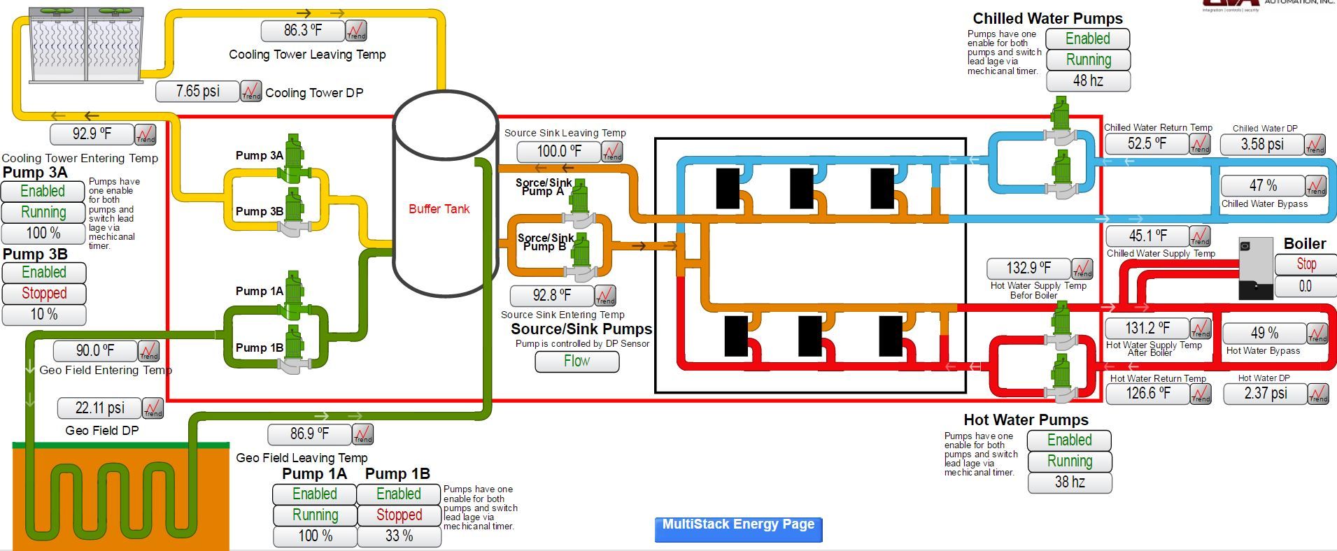
.. also note the delta T's on the heating and chilled water loop and the amount of water being bypassed. At that moment I took the shot, it had just cycled off. Setpoint is 130F. Design delta T is 20F, when 2 compressors are running on a single module, 10F for one compressor. That correlates to approx. 60 GPM for a single module, or about 1.2 GPM per ton of heating capacity. Condensers are oversized as expected for that low flow rate.
I'll have to study that variable flow guide that was linked in my other related thread.


 Reply
Reply

 Professional Member*

 aquadave liked this post.


