-

Originally Posted by
JayMan7

You would think that would be true, but it isn't. Trane eevs use only 2 inputs. The temperature post eev and the temperature post evap coil. I think the engineers are making the assumption that temperature post eev has 0 superheat so PT relationship applies. Infer pressure from that, and then you calculate superheat by post evaporator temperature.
As far as making them close on power off...be smart about how you do that. If the eev closes on power down it needs to be stepped partially open immediately on power up. Trane eevs are horrible about causing units to pump down and then lock out because they wait too long to open. I think they should open a little on start up and then adjust later after the inputs have stabilized.
Sent from my SM-G960U using Tapatalk
You know, sometimes I skim through messages too quickly. I misread your post the first time and thought you were suggesting to have one temp sensor on the liquid line while the other after the evap coil. Having just revisited your post right now, What you ACTUALLY posted makes a lot more sense.  I dont see why picking up the saturated condition after the EXV wouldnt work and I think thats what that article was touching on,that I havent found yet (but havent put enough effort into it to consider it lost yet). Regardless, at this point it looks like that article isnt really going to add anything beneficial, I think it was really just opening up the mind that it could be done using that method.
Now that we (I) are all on the same page, seems like a good cost effective and easiest way to go. 
10 degrees to start seems like it should get you in the ballpark. You could always adjust it after you get it running in real world conditions and can see how fast its responding and what refrigerant conditions look like at the compressor.
Sent from my iPhone using Tapatalk
Quickly, I must hurry, for there go my people and I am their leader!
-
-
Post Likes - 2 Likes, 0 Dislikes
-
Originally Posted by
thatguy
You know, sometimes I skim through messages too quickly. I misread your post the first time and thought you were suggesting to have one temp sensor on the liquid line while the other after the evap coil. Having just revisited your post right now, What you ACTUALLY posted makes a lot more sense.
I dont see why picking up the saturated condition after the EXV wouldnt work and I think thats what that article was touching on,that I havent found yet (but havent put enough effort into it to consider it lost yet). Regardless, at this point it looks like that article isnt really going to add anything beneficial, I think it was really just opening up the mind that it could be done using that method.
Now that we (I) are all on the same page, seems like a good cost effective and easiest way to go.
10 degrees to start seems like it should get you in the ballpark. You could always adjust it after you get it running in real world conditions and can see how fast its responding and what refrigerant conditions look like at the compressor.
Sent from my iPhone using Tapatalk
To be fair I probably could have worded it a little more clearly 
Sent from my SM-G960U using Tapatalk
"I think Quantum tunneling would work great...

"
"Call a technician for God's sake. Or we'll see you on the news or the Dark Side of the Moon."
-
Post Likes - 1 Likes, 0 Dislikes
-
Originally Posted by
JayMan7
To be fair I probably could have worded it a little more clearly
Sent from my SM-G960U using Tapatalk
That would have taken all the fun out of it. I scratched my head so hard trying to figure out how you were proposing to use liquid temp as a calculation, wondering what I could possibly be missing. Then it dawned on me to just look at what we actually would need to make it work and only realized you were on the right track the whole time when I went to correct the sensor placement in your post. LOL
I went on an interesting little adventure down the google hole along my way. It doesnt seem very common to control a EXV using the Two Temp method.
Liebert
Sanhua
Sporlan
Carel
Boumatic
Emerson
All appear to use pressure and an evap outlet temperature to control theirs superheat controllers (at least of their products that I looked at). P&T from what I can see appear to be the dominant method of doin this, but I could see it becoming a bit complex trying to program it. Im thinking the two temperatures method is still the easiest solution for a backyard build type project.
You could probably get away with making a HP using one EXV if you place temp sensors on both sides of it and after each coil, and operate the leaving side of the liquid line as a low pressure saturated line that leads to the evaporator. Isnt this what typical ductless splits do? Hence the need to insulate both lines? If the EXV was placed in the condenser section then it would reduce noise inside at the AHU. Heating or cooling mode would simply select whatever inputs are required to control the EXV.
Is this for a class project?
Sent from my iPhone using Tapatalk
Quickly, I must hurry, for there go my people and I am their leader!
-
Post Likes - 2 Likes, 0 Dislikes
-
Originally Posted by
thatguy
You could probably get away with making a HP using one EXV if you place temp sensors on both sides of it and after each coil, and operate the leaving side of the liquid line as a low pressure saturated line that leads to the evaporator. Isn’t this what typical ductless splits do? Hence the need to insulate both lines? If the EXV was placed in the condenser section then it would reduce noise inside at the AHU. Heating or cooling mode would simply select whatever inputs are required to control the EXV.
Is this for a class project?
Yes it is for a class training.
Actually this is what I was thinking of, as the heating and cooling are a must.
So I was thinking of making the same set up with same parts (2 temp sensors and only one EEV), because it will be complicated for me to change the orientation of the sensors (tell the controller which is the IN and which is the OUT for each mode) in case of refrigerant changing direction.
I am taking the absolute value for the difference in temperature "|Tout - Tin|=Ts". So if the refrigerant flowed in the other direction it will still go through the same EEV and the EEV will still regulate the flow in the cycle, to maintain the 10 °F superheat.
Am I right or not making any sense 
-
Originally Posted by
shamooooot
Yes it is for a class training.
Actually this is what I was thinking of, as the heating and cooling are a must.
So I was thinking of making the same set up with same parts (2 temp sensors and only one EEV), because it will be complicated for me to change the orientation of the sensors (tell the controller which is the IN and which is the OUT for each mode) in case of refrigerant changing direction.
I am taking the absolute value for the difference in temperature "|Tout - Tin|=Ts". So if the refrigerant flowed in the other direction it will still go through the same EEV and the EEV will still regulate the flow in the cycle, to maintain the 10 °F superheat.
Am I right or not making any sense
Not making sense... or Im misunderstanding you...
So you want to use one EEV and only two sensors total? I dont see that working but I may be misunderstanding your idea. Let me explain how I visualized it working and let me know if it falls in line with your thoughts. Perhaps you could explain it in a similar method if your idea was different. Feel free to use proper coding language in your example. It would be good for me to see it anyway. Its something Ive wanted to learn just never had the time yet so have always resorted to modifying other code to suit my needs. Ill do my best to respond using the proper language as we hash out ideas.
Can you monitor the status of your reversing valve with a digital input? Lets say the reversing valve inputs to DI1 for this example
If DI1 = on, then follow program Cool
If DI1 = off, then follow program Heat
Program Cool =
If |T1out - T2in|=10+, then open EEV
If |T1out - T2in|=10-, then close EEV
Program Heat =
If |T3out - T4in|=10+, then open EEV
If |T3out - T4in|=10-, then close EEV
Now again, understand I dont code, the actual code to run this would look different but Im hopeful this example will work to explain my idea as to how I would see it working with 4 thermistors.
The reason I dont see only two thermistors working on a HP application is because when the refrigerant changes direction, the saturated side of the EEV where one of your thermistors is located now becomes the subcooled side. You cant use the subcooled measurement to control superheat. (Well... Perhaps you can, I shouldnt say never, but it would come with great difficulty and high cost. Unless there is a better way than I can think of then I dont see it being very reliable and It would be prone to failure)
You may be able to use only 3 thermistors if you put the evaporator leaving sensor on the true compressor suction line instead of the evaporator outlet. You would want to increase your superheat a bit. The response would be slower but you MAY be able to tweak out the hunting in the software.... but it also opens you up to other issues so it would come at a potentially high cost if it doesnt work as planned.
Sent from my iPhone using Tapatalk
Quickly, I must hurry, for there go my people and I am their leader!
-
Post Likes - 1 Likes, 0 Dislikes
-
that's very good explanation, it actually gave me the idea of what if we use the temperature difference to tell the controller that we are in heating or in cooling mode?:
If Tin<Tout, then follow program cool
If Tin>Tout, then follow program heat
Program Cool =
If Tout - Tin=10+, then open EEV
If Tout - Tin=10-, then close EEV
Program Heat =
If Tin - Tout=10+, then open EEV
If Tin - Tout=10-, then close EEV
-
Originally Posted by
shamooooot
that's very good explanation, it actually gave me the idea of what if we use the temperature difference to tell the controller that we are in heating or in cooling mode?:
If Tin<Tout, then follow program cool
If Tin>Tout, then follow program heat
Program Cool =
If Tout - Tin=10+, then open EEV
If Tout - Tin=10-, then close EEV
Program Heat =
If Tin - Tout=10+, then open EEV
If Tin - Tout=10-, then close EEV
There probably nothing wrong with looking at the difference. It would save an input if you needed it for something else. The command would be a little delayed while if figured out what is happening before it can start to react so that may become problematic, but Im not convinced the delay would be significant enough to cause issues. I always prefer to reduce the thinking required by the computer and run a hard wire directly. Theres no confusion, it has a clear on or off command, and it can respond immediately right from the very beginning. Im not sure what the refresh rate would be on your program though so maybe its really not an issue at all.
I made a quick sketch ... sigh, I should label the sensors according to how weve previously discussed... Ill draw a new one up when I get the chance.
Sent from my iPhone using Tapatalk
Quickly, I must hurry, for there go my people and I am their leader!
-
Post Likes - 1 Likes, 0 Dislikes
-
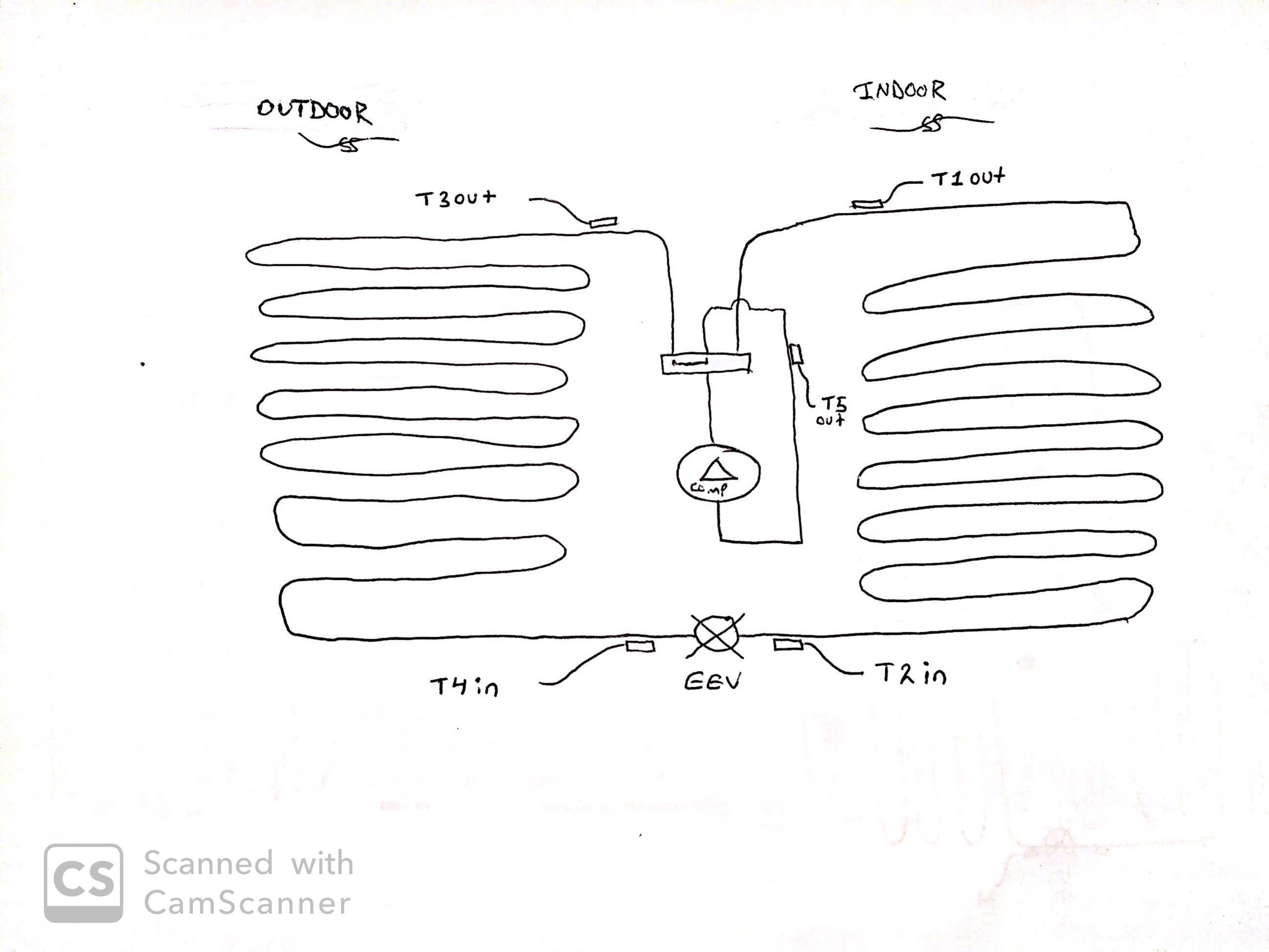
So if you were to use 4 thermistors then you would use T1, T2, T3, T4
If you use only three thermistors then you would need T2, T4, T5
Sent from my iPhone using Tapatalk
Quickly, I must hurry, for there go my people and I am their leader!
-
Post Likes - 1 Likes, 0 Dislikes
-
Originally Posted by
thatguy
So if you were to use 4 thermistors then you would use T1, T2, T3, T4
If you use only three thermistors then you would need T2, T4, T5
Sent from my iPhone using Tapatalk
Thank you for all your efforts!
Can you walk me through your sketch?, I am a bit confused with it.
The outdoor unit has its own system and its own expansion valve. Is it safe to say that I can use the T1out and the T2in only, as my inputs ?
-
Electronic Expansion Valves
Originally Posted by
shamooooot
Thank you for all your efforts!
Can you walk me through your sketch?, I am a bit confused with it.
The outdoor unit has its own system and its own expansion valve. Is it safe to say that I can use the T1out and the T2in only, as my inputs ?
Does this help?
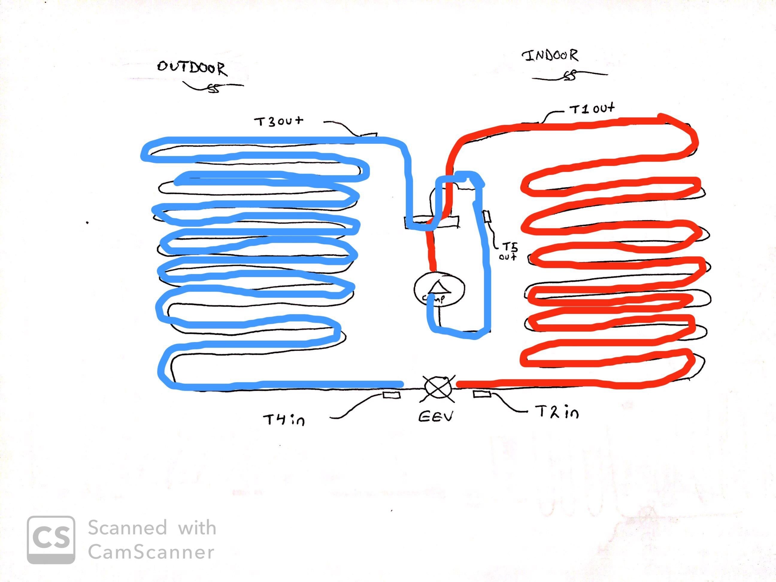
I drew it in heating mode because I mentioned previously in my example that Reversing valve input would be heat when Unenergized.
Simply swap the hot gas out and the suction in through the reversing valve to change to cooling mode. I had drawn the little slider inside of it to indicate the path of the suction gas on the first picture. That slider is true to life as to how they work. Slide that over to connect the middle and right pipes (instead of the middle and left pipes) and you will be in cooling mode.
You will see that your thermistor is not in the right spot to measure superheat when you switch to cooling mode so if you want both heat and cooling then you need to add at least one more thermistor. So you can monitor the refrigerant temperature at the outlet of the EEV after the refrigerant changes direction.
Let me know if you still have questions.
Sent from my iPhone using Tapatalk
Quickly, I must hurry, for there go my people and I am their leader!
-
Post Likes - 1 Likes, 0 Dislikes
-
We install walk in freezer and coolers that use a 5V DC EEV, the EEV will open proportionally to the strength of the signal between 0 and 5V, if they all are like that then an Arduino would be perfect for them
https://www.heatcraftrpd.com/QRC/res/pdf/H-IM-QRC.pdf
thats the link to the manual for the control module, should help you get an understanding of how to program the arduino at least on the cooling side, it has part numbers for the EEVs/sensors towards the end you could probably find a manual on those or something similar but for heat pumps that will help you get a base for what parameters you are going to want to use
-
Post Likes - 1 Likes, 0 Dislikes
-
Originally Posted by
KittySwampAss
We install walk in freezer and coolers that use a 5V DC EEV, the EEV will open proportionally to the strength of the signal between 0 and 5V, if they all are like that then an Arduino would be perfect for them
https://www.heatcraftrpd.com/QRC/res/pdf/H-IM-QRC.pdf
thats the link to the manual for the control module, should help you get an understanding of how to program the arduino at least on the cooling side, it has part numbers for the EEVs/sensors towards the end you could probably find a manual on those or something similar but for heat pumps that will help you get a base for what parameters you are going to want to use
Hmm interesting so there's no stepper motor power head on those eev's? Do you have a pic of the eev?
Sent from my SM-G960U using Tapatalk
"I think Quantum tunneling would work great...
"
"Call a technician for God's sake. Or we'll see you on the news or the Dark Side of the Moon."
-
Originally Posted by
JayMan7
Hmm interesting so there's no stepper motor power head on those eev's? Do you have a pic of the eev?
Sent from my SM-G960U using Tapatalk
It sounds to me like it is a control board that has a 0-5v DC signal input from the pressure transducer , the control board converts that to a equivalent number of steps output to the EEV.
The expansion valve position can be monitored from the LED display pressing the MONITOR button and scrolling to ESP. This will indicate the number of steps the valve is open.
This can also be checked by using the EXV test pins on the board. This is indicated by a 0 to 5 volts DC signal. At 0 volts the valve is closed and at 5 volts the valve is fully open. At values between 0 and 5 volts, the valve will be opened proportionately.
It says its a bipolar motor with two windings controlling the EEV.... sounds like a stepper to me.
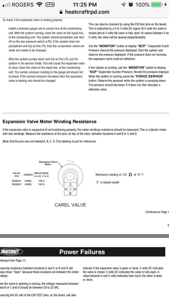
I havent read the whole thing, just skimmed some parts of the manual hat looked like it would include this info, so I may have missed something here but looks like a normal stepper to me, however it also looks fairly easily replicated with some programming and an Arduino
Sent from my iPhone using Tapatalk
Quickly, I must hurry, for there go my people and I am their leader!
-
Post Likes - 1 Likes, 0 Dislikes
-
True 0-5VDC would make more sense as a signal circuit and not as the actual driver of the eev
Sent from my SM-G960U using Tapatalk
"I think Quantum tunneling would work great...
"
"Call a technician for God's sake. Or we'll see you on the news or the Dark Side of the Moon."


 Reply
Reply
 Professional Member


 shamooooot liked this post.
